Designing DC-DC converters using TI TPS61200 controller
About a year ago, while researching low-startup-voltage DC-DC converters, I came across Texas Instruments’ TPS61200. This monolithic synchronous rectifier boost converter offers several notable features.
First, its input voltage range starts as low as 0.3V, making it possible to operate the converter from low-voltage sources such as a single solar cell or a supercapacitor. Second, the converter is powerful—delivering up to 1.8A under certain input/output voltage combinations. (The word “certain” is key here—see below for an explanation.)
Another valuable feature is its ability to down-regulate the output when the input voltage exceeds the output voltage. For example, you can configure the converter to run from a single-cell Li-ion or Li-poly battery and provide a stable 3.3V across the entire 4.2V–2.7V discharge range.
Additionally, the controller includes a built-in undervoltage lockout feature: the minimum input voltage—below which the controller shuts itself off—can be set using a simple voltage divider. This is especially useful when a rechargeable battery is used as the power source.
The TPS61200 also has pins for enable/disable control and power-saving mode selection. The device is available in two fixed output voltage versions—3.3V and 5V—as well as an adjustable version. The maximum input voltage is 5.5V, and the minimum output voltage for the adjustable variant is specified at 1.8V.
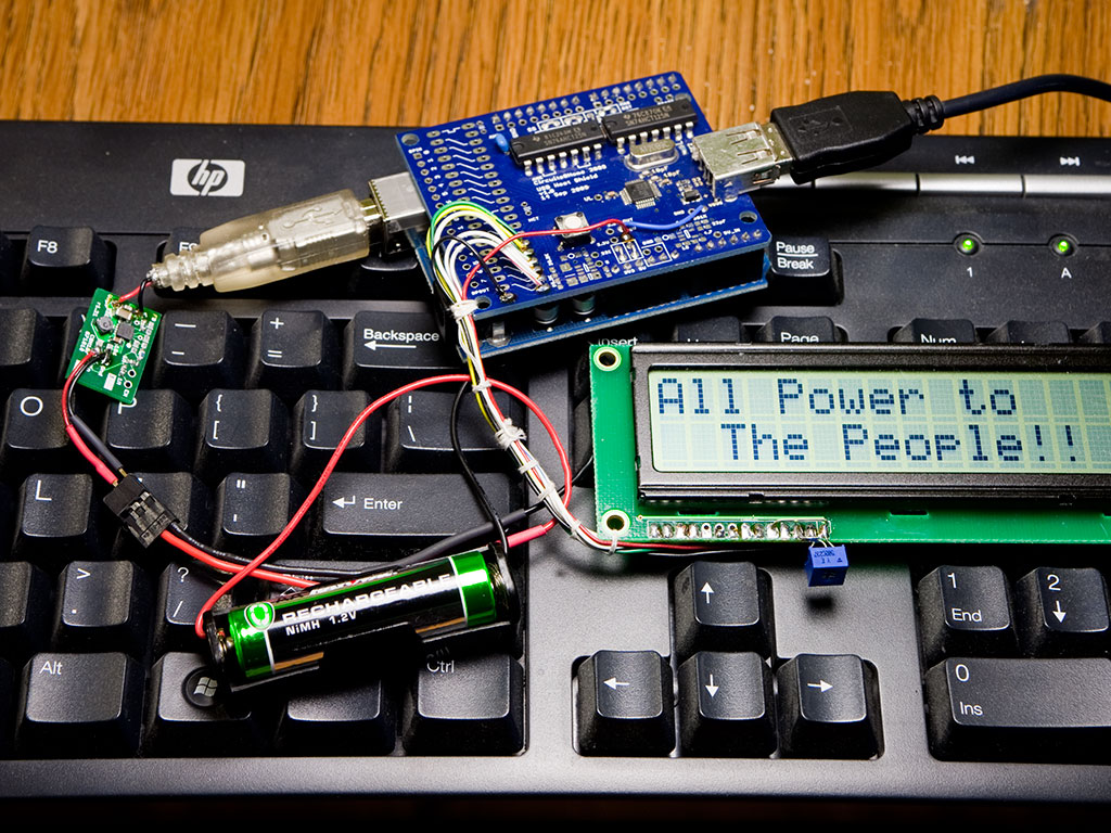
After extensive prototyping and testing, I arrived at a layout that works well. The result is shown in the title image: an Arduino Duemilanove board, USB Host Shield, LCD display, and USB keyboard—all powered by a single 1.2V NiMH AA cell. The circuit that makes this possible is visible on the left side of the image, connected between the battery and the USB-B connector, which in this setup is used as a 5V power input for the Arduino.
The runtime of this setup using a freshly charged 1800 mAh NiMH cell is about 6 hours, which makes it quite practical. However, it's important to note that when the input voltage is much lower than the output voltage, efficiency decreases significantly (see Figure 8 in the datasheet). Using three NiMH cells in series or a single-cell Li-Poly battery is a much better option for 5V output. Even four NiMH cells will work if the load is light. In down-conversion mode, power losses in the converter increase, and I found that the chip becomes quite warm when supplying 200 mA or more while stepping down the voltage.
 Another non-obvious characteristic of this controller is the relationship between maximum output current and input voltage. Figure 1 in the datasheet shows that for input voltages up to 0.6 V, the available output current is quite low—less than 50 mA. This is the level of current one should expect when operating the converter from a single 0.55 V solar cell. Voltage drop due to battery discharge also needs to be considered. For example, a fully charged Li-Poly cell has a terminal voltage of 4.2 V, which, according to Figure 1, allows for an output current of up to 1500 mA. However, at the end of the discharge cycle (2.7 V), the maximum output current drops to around 800 mA. This lower value should be treated as the safe maximum current across the entire battery voltage range.
The controller includes built-in over-current and over-temperature protection, so experimenting with heavy loads is unlikely to damage it. In my tests, it remained reasonably cool with output currents up to 1 A. Higher currents are certainly possible when the input-to-output voltage ratio is low and sufficient cooling is provided.
Now let’s talk about power source selection. A pair of AA or AAA alkaline batteries works well for generating 3.3 V, while three cells are suitable for 5 V output. If minimizing weight or circuit volume is a priority, even a single cell can be used. The absolute maximum input voltage for the TPS61200 is specified at 7 V; therefore, for maximum runtime, up to four AA cells can be connected in series. However, this comes with significant efficiency loss at the beginning of the discharge cycle—until the input voltage drops below the output voltage.
Solar cells and supercapacitors are also viable options when powering very light loads. Rechargeable batteries are another good choice. However, because the TPS61200 can operate with input voltages as low as 250 mV, special precautions are necessary when using rechargeables to avoid excessive discharge and potential battery damage.
Draining rechargeable cell below its end-of-discharge voltage may cause damage to the cell. As a result, a cell may become non-rechargeable and Lithium cell may even overheat and catch fire. For NiMH cell, end-of-discharge is 0.8V; for Li-Poly cells recommended end-of-discharge is 2.5-2.7V. To work properly with rechargeable power sources TPS61200 has built-in undervoltage lockout circuitry – when voltage on UVLO pin drops below 250mV, the converter turns off. Therefore, desired end-of-discharge voltage can be easily set with voltage divider ( R3, R4 of the schematic). UVLO pin also has hysteresis of 50mv and this hysteresis gets multiplied by dividers’ ratio; for example, when UVLO is set to 2.5V, minimum turn-on voltage of the converter will be 3V. Capacitor C4 takes care of this issue by shorting resistor R3 during turn-on.
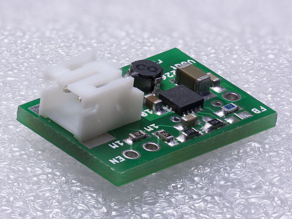
The close-up image shows a TPS61200-based DC-DC converter designed for a 5 V output with a Li-Poly input. The blue component marked “0” near the lower-right corner of the PCB is a jumper across R5 (I'm using the fixed-output TPS61202 in this build). The two resistors placed along the edge of the board form the UVLO voltage divider.
The JST connector’s polarity is compatible with those found on many single-cell Li-Poly batteries commonly available on the market. However, since no universal polarity standard exists for these connectors, it’s important to verify the battery connector’s polarity before use.
Project files are available in the Resources section. The TPS61200 is provided in a 10-pin QFN package with a thermal pad on the bottom, which must be soldered to the PCB for proper heat dissipation. Other components used are in 0603 and 1206 sizes. Both surface-mount and through-hole JST connectors can be used on the input side.
This project demonstrates the impressive capabilities of the TPS61200 family in enabling efficient power conversion from a wide range of low-voltage sources. Whether you're building compact battery-powered devices, experimenting with solar or supercapacitor input, or simply looking for a robust 5 V supply, this converter offers a flexible and reliable solution. With built-in protections and support for adjustable undervoltage lockout, it's well-suited for both prototyping and real-world applications. I hope the information and resources provided here help you get started on your own designs—feel free to explore, adapt, and improve upon the ideas presented.