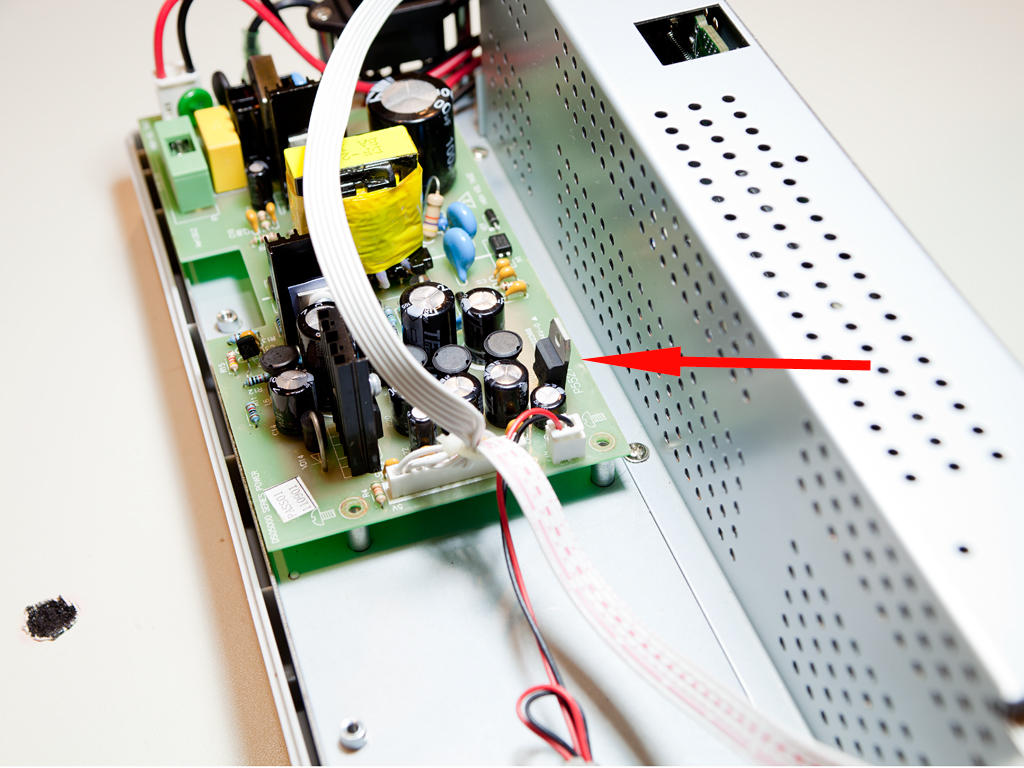
 This simple modification, originally described by tinhead on the EEVBlog forum, is intended to make the built-in cooling fan quieter. A common issue with cooling fans is the noise they produce, and a typical solution is to reduce the voltage (and therefore the current) supplied to the fan, causing it to spin more slowly. The Hantek DSO5000-series oscilloscopes feature a three-terminal 12V voltage regulator dedicated to the fan (indicated by an arrow in the title image). To adjust the fan voltage, I simply need to replace the regulator labeled U7 on the power supply PCB.
 Some time ago, I realized that I needed to add a digital oscilloscope to my set of instruments. A DSO is handy for making measurements and capturing screenshots—something I've been doing a lot lately. After comparing the specifications of current models from several manufacturers, I chose the Hantek DSO5102B. The main reasons for selecting this model were its cost, screen size, and strong potential for hacking—though not necessarily in that order.
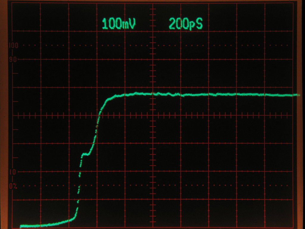 While making some measurements today, I noticed a strange reflection in the signal generated by my Tektronix 7S12 TDR sampling plugin. At first, it looked like a bad connection at the output of the loop-through S-6 sampling head. However, after further testing, it turned out to be a more serious flaw.
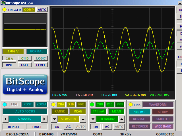 I was experimenting with some analog circuits and, while reading this article, built a test circuit to better understand how an operational amplifier maintains linearity using negative feedback. During this process, I ended up generating enough material for a short article—so I wrote one, hoping it might be interesting to someone. I also made a video, a link to which is available at the end of the article.
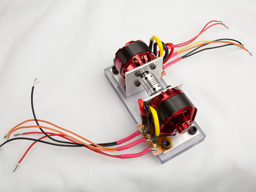 Two brackets, made from 2″ aluminum angle profile, hold 50-size brushless outrunner motors rated at 100 A each. The brackets are bolted to a 0.5″ polycarbonate base, and the motor shafts are connected via a flexible coupler. Contact plates are mounted next to each motor—this makes it easy to swap out a motor if one burns out. High-current wires are soldered to the female contacts. I’m using double wires to increase current-carrying capacity and to allow monitoring half the current with my 50 A current probe.