 In this short article, I’d like to share a trick I learned today while checking the power supply of my trusty Tektronix 7104 oscilloscope. Step A2 of the calibration section in the manual calls for measuring and adjusting the pre-regulated 109V voltage at test point
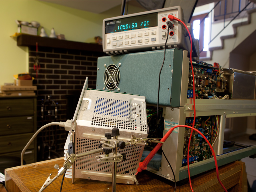
 TP1326. Normally, accessing this test point requires removing the power supply cover, which takes time and exposes high voltages. The test setup shown in the title picture demonstrates how to access this test point while keeping the power supply cover in place.
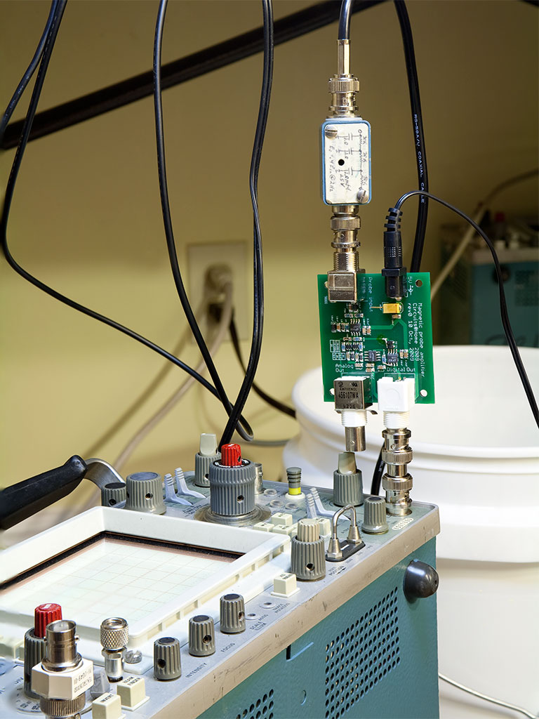 When working with switching power supplies or high-frequency circuits, getting a clean, reliable oscilloscope trigger can be surprisingly tricky. Standard probes often struggle with noise and interference, especially when trying to capture small ripple or switching artifacts. Fortunately, there are clever solutions hidden in the deep archives of application notes. In this post, I’ll share a particularly elegant trigger probe circuit originally developed by Jim Williams, along with some practical tips for building and adapting it with modern, easily available components.
 One of the most valuable instruments in my collection is the Tektronix current measurement system, which consists of an AM503 probe amplifier and the accompanying A6302 AC/DC probe. While the probe itself doesn’t need much attention beyond the occasional wipe to remove dirt from the jaws, the amplifier recently became quite noisy in several attenuator positions. So, I decided it was time for a thorough spring cleaning.
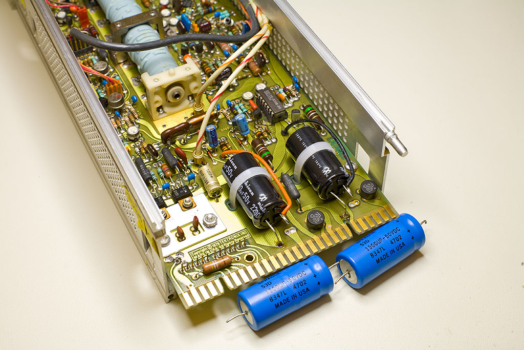