Robotic Arm Inverse Kinematics on Arduino
Ever wanted to control a robotic arm with precision — without relying on a bulky PC? In this project, I’m building a fully Arduino-powered controller for my Lynxmotion AL5D arm, starting with one of the most important challenges: inverse kinematics. In this post, I’ll walk you through the first working version of the code, the resources that helped me, and a few tips if you’re thinking of tackling IK yourself!
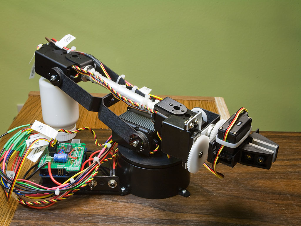
I’m the proud owner of a Lynxmotion AL5D robotic arm. The parts kit is extremely well made, and the arm itself is both strong and versatile. I wanted my setup to be portable and independent from bulky computers, but none of the available controllers offered the flexibility I needed. So, I decided to build my own controller — based on the Arduino platform. This post shares the first big milestone in that project: working inverse kinematics (IK) code to position the arm.
In robotics, inverse kinematics is a method for positioning the tip of a linked structure in 3D space by calculating joint angles based on the tip’s X, Y, and Z coordinates. There’s a ton of information online about it — for example, this introductory article explains the basics using simple trigonometry.
To move the arm, six servos need to be controlled (five if you don’t count wrist rotation). Since calculating servo angles eats up quite a bit of processing time, I decided not to drive the servos directly from the Arduino pins. Instead, I built a simple servo shield based on the Renbotics schematic and library code. I only built half the circuit, using a single 4017 counter — which gives me seven servo channels. More than enough!
Besides the article linked above, two other resources were incredibly helpful during development. The first is Micromega Application Note 44 (local copy), which walks through IK equations for a similar robotic arm — plus, they’ve got a great video showing it in action. It’s worth noting that the AL5D’s gripper has much simpler geometry, so second-order polynomial calculations aren’t necessary. The second resource is a Lynxmotion project page with an Excel spreadsheet, which I sadly can't locate at the moment. I borrowed many formulas from that spreadsheet for my code, and also used it to debug after tweaking the arm’s dimensions.
Below is the first working draft of my IK code. You can use it as-is or turn it into a proper Arduino library. Just a word of caution: no boundary checks are in place yet, so it’s pretty easy to accidentally send the arm flying into your forehead or smash your control board. Use responsibly! 😅
The code uses single-precision floating-point math, which seems more than adequate for this application.
#include <servoShield.h>

/* Servo control for AL5D arm */

/* Arm dimensions( mm ) */
#define BASE_HGT 67.31      //base hight 2.65"
#define HUMERUS 146.05      //shoulder-to-elbow "bone" 5.75"
#define ULNA 187.325        //elbow-to-wrist "bone" 7.375"
#define GRIPPER 100.00          //gripper (incl.heavy duty wrist rotate mechanism) length 3.94"

#define ftl(x) ((x)>=0?(long)((x)+0.5):(long)((x)-0.5))  //float to long conversion

/* Servo names/numbers */
/* Base servo HS-485HB */
#define BAS_SERVO 0
/* Shoulder Servo HS-5745-MG */
#define SHL_SERVO 1
/* Elbow Servo HS-5745-MG */
#define ELB_SERVO 2
/* Wrist servo HS-645MG */
#define WRI_SERVO 3
/* Wrist rotate servo HS-485HB */
#define WRO_SERVO 4
/* Gripper servo HS-422 */
#define GRI_SERVO 5

/* pre-calculations */
float hum_sq = HUMERUS*HUMERUS;
float uln_sq = ULNA*ULNA;

ServoShield servos;                       //ServoShield object

void setup()
{
  servos.setbounds( BAS_SERVO, 900, 2100 );
  servos.setbounds( SHL_SERVO, 1000, 2100 );
  servos.setbounds( ELB_SERVO, 900, 2100 );
  servos.setbounds( WRI_SERVO, 600, 2400 );
  servos.setbounds( WRO_SERVO, 600, 2400 );
  servos.setbounds( GRI_SERVO, 600, 2400 );
  /**/
  servos.start();                         //Start the servo shield
  servo_park();
  Serial.begin( 115200 );
  Serial.println("Start");
  delay( 500 );
}

void loop()
{

  //zero_x();
  //line();
  circle();
 }

/* arm positioning routine utilizing inverse kinematics */
/* z is height, y is distance from base center out, x is side to side. y,z can only be positive */
//void set_arm( uint16_t x, uint16_t y, uint16_t z, uint16_t grip_angle )
void set_arm( float x, float y, float z, float grip_angle_d )
{
  float grip_angle_r = radians( grip_angle_d );    //grip angle in radians for use in calculations
  /* Base angle and radial distance from x,y coordinates */
  float bas_angle_r = atan2( x, y );
  float rdist = sqrt(( x * x ) + ( y * y ));
  /* rdist is y coordinate for the arm */
  y = rdist;
  /* Grip offsets calculated based on grip angle */
  float grip_off_z = ( sin( grip_angle_r )) * GRIPPER;
  float grip_off_y = ( cos( grip_angle_r )) * GRIPPER;
  /* Wrist position */
  float wrist_z = ( z - grip_off_z ) - BASE_HGT;
  float wrist_y = y - grip_off_y;
  /* Shoulder to wrist distance ( AKA sw ) */
  float s_w = ( wrist_z * wrist_z ) + ( wrist_y * wrist_y );
  float s_w_sqrt = sqrt( s_w );
  /* s_w angle to ground */
  //float a1 = atan2( wrist_y, wrist_z );
  float a1 = atan2( wrist_z, wrist_y );
  /* s_w angle to humerus */
  float a2 = acos((( hum_sq - uln_sq ) + s_w ) / ( 2 * HUMERUS * s_w_sqrt ));
  /* shoulder angle */
  float shl_angle_r = a1 + a2;
  float shl_angle_d = degrees( shl_angle_r );
  /* elbow angle */
  float elb_angle_r = acos(( hum_sq + uln_sq - s_w ) / ( 2 * HUMERUS * ULNA ));
  float elb_angle_d = degrees( elb_angle_r );
  float elb_angle_dn = -( 180.0 - elb_angle_d );
  /* wrist angle */
  float wri_angle_d = ( grip_angle_d - elb_angle_dn ) - shl_angle_d;

  /* Servo pulses */
  float bas_servopulse = 1500.0 - (( degrees( bas_angle_r )) * 11.11 );
  float shl_servopulse = 1500.0 + (( shl_angle_d - 90.0 ) * 6.6 );
  float elb_servopulse = 1500.0 -  (( elb_angle_d - 90.0 ) * 6.6 );
  float wri_servopulse = 1500 + ( wri_angle_d  * 11.1 );

  /* Set servos */
  servos.setposition( BAS_SERVO, ftl( bas_servopulse ));
  servos.setposition( WRI_SERVO, ftl( wri_servopulse ));
  servos.setposition( SHL_SERVO, ftl( shl_servopulse ));
  servos.setposition( ELB_SERVO, ftl( elb_servopulse ));

}

/* move servos to parking position */
void servo_park()
{
  servos.setposition( BAS_SERVO, 1715 );
  servos.setposition( SHL_SERVO, 2100 );
  servos.setposition( ELB_SERVO, 2100 );
  servos.setposition( WRI_SERVO, 1800 );
  servos.setposition( WRO_SERVO, 600 );
  servos.setposition( GRI_SERVO, 900 );
  return;
}

void zero_x()
{
  for( double yaxis = 150.0; yaxis < 356.0; yaxis += 1 ) {
    set_arm( 0, yaxis, 127.0, 0 );
    delay( 10 );
  }
  for( double yaxis = 356.0; yaxis > 150.0; yaxis -= 1 ) {
    set_arm( 0, yaxis, 127.0, 0 );
    delay( 10 );
  }
}

/* moves arm in a straight line */
void line()
{
    for( double xaxis = -100.0; xaxis < 100.0; xaxis += 0.5 ) {
      set_arm( xaxis, 250, 100, 0 );
      delay( 10 );
    }
    for( float xaxis = 100.0; xaxis > -100.0; xaxis -= 0.5 ) {
      set_arm( xaxis, 250, 100, 0 );
      delay( 10 );
    }
}

void circle()
{
  #define RADIUS 80.0
  //float angle = 0;
  float zaxis,yaxis;
  for( float angle = 0.0; angle < 360.0; angle += 1.0 ) {
      yaxis = RADIUS * sin( radians( angle )) + 200;
      zaxis = RADIUS * cos( radians( angle )) + 200;
      set_arm( 0, yaxis, zaxis, 0 );
      delay( 1 );
  }
}
Here’s a quick walkthrough of how the code works:
The coordinate space matches the one used in Micromega AN44. The set_arm() function takes three coordinates and a grip angle, then sets the servo angles for the base, elbow, shoulder, and wrist. Arm dimensions are defined in millimeters at the top of the sketch.
To demonstrate functionality, I wrote three small test functions:
zero_x()moves the arm in a straight line along the y-axis.line()sweeps the arm side to side.circle()moves the arm in a circular path in the y-z plane.
In all three cases, the wrist angle is set to 0 degrees by default, but you can change it to make the motions even more interesting.
This is just the beginning of the journey. With working inverse kinematics in place, the next steps are adding boundary checking, smoothing out motion, and maybe even building a full graphical interface for the controller. I’ll be posting updates as the project evolves — stay tuned! And if you’ve tackled IK on Arduino or have tips to share, I’d love to hear about your experiences in the comments.