Repairing Front Panel Buttons of a Tektronix 7904 Oscilloscope
I’m a proud owner of several Tektronix 7000-series mainframes. Among them, the 7904— a 500 MHz, 4-compartment oscilloscope—for many years served as my bench workhorse. The screen is large enough, the bandwidth is adequate for the majority of tasks I perform, and the absence of a cooling fan makes it pleasantly quiet. Additionally, the instrument is relatively lightweight compared to other 7000 mainframes and has legs mounted on the rear panel, allowing it to stand vertically on the floor.
I became increasingly annoyed by the malfunctioning right-side buttons of both the vertical and horizontal mode selectors—they failed to lock in place—so I decided my scope deserved some TLC. Along with fixing the buttons, I also planned to replace a few dead illumination bulbs with LEDs.
The mode switches are dual, with one switch in each pair dedicated to turning the illumination bulb on or off. These bulbs are powered by 5 V, and dimming is implemented using two diode drops. A 3 V LED limited to 10 mA by a resistor works fine and even offers a bit of dimming. Also, the power consumption of an LED is about 8% of that of a bulb.
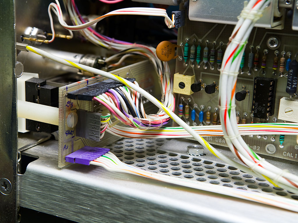
The front panel buttons are mounted on a narrow PCB (called the “A3 – Front Panel Interconnect Board” in the service manual) that runs across the middle of the front panel. It can be easily accessed after removing the side panels. Several cables connect to the board from both sides, so it’s a good idea to mark them before disconnecting. The title picture shows the left side of the board (near the horizontal bay “B”) with my marks on it. After disconnecting the cables, I carefully moved the PCB toward the rear and to the side. The board is fairly flexible and somewhat accessible from the top of the instrument.
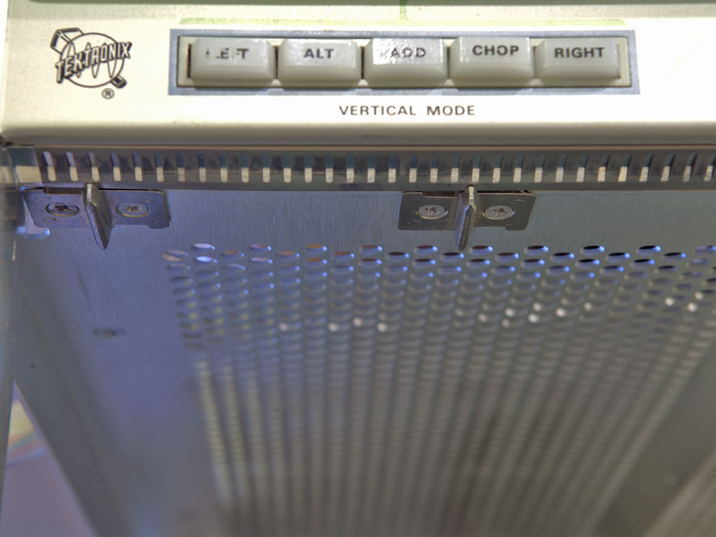
The button assembly is held in place by screws that also secure the upper plug-in guide bars in the plug-in compartment. The picture below shows the position of the left-side screws (holding the vertical mode buttons). After removing four Phillips-head screws, I pulled the vertical mode button assembly out of the chassis, carefully guiding it around cables, structural members—and the occasional dead mouse.
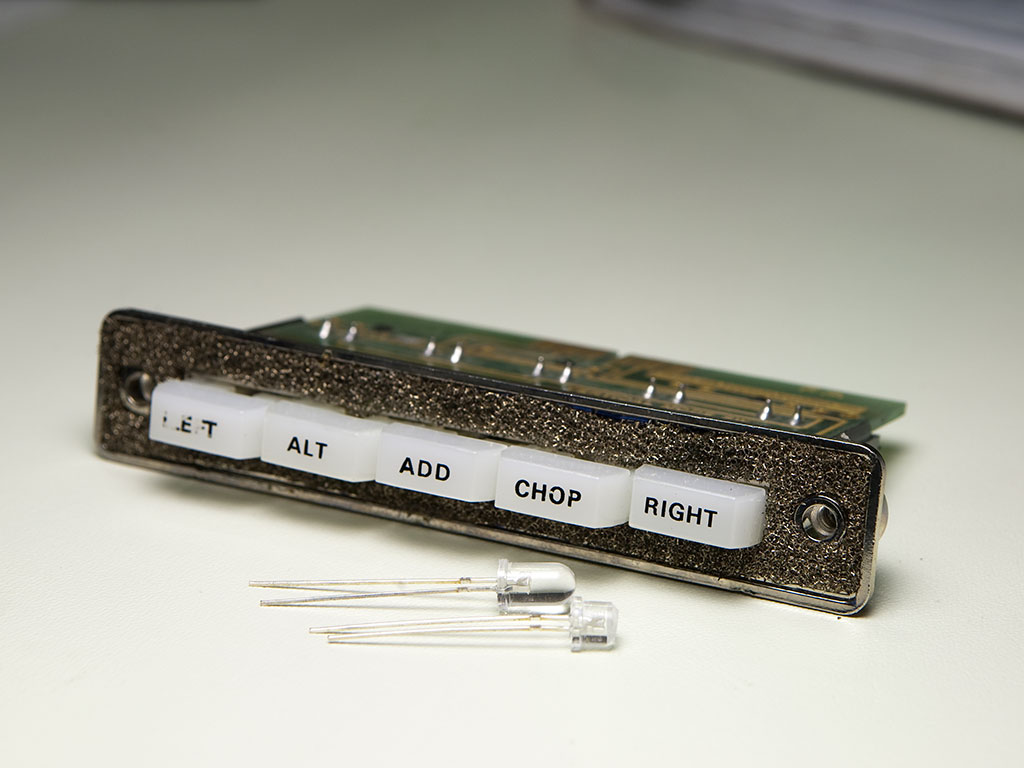
The issue with the buttons not locking was caused by a small piece of loose plastic obstructing the mechanism. After blowing compressed air through the switches and applying a drop of DeOxit D100L, the block was as good as new. For the illumination, I repurposed a standard 5 mm white LED from Amazon, reshaped using a Dremel tool. The pictures below show both the original and modified LEDs, as well as the LED placement on the board. In the second picture, the original bulb can be seen to the right of the LED.

Overall, I’m very pleased with this modification. The illumination is soft, with a slight bluish tint that— in my opinion—matches the aluminum faceplate better than the “straw yellow” color of the original bulbs. It also dims nicely using the standard illumination rotary switch on the instrument. I ran out of LEDs, so I couldn’t replace all the bulbs at once—but one day I surely will.