Programming Voltage Limiter for Newer PIC Microcontrollers
Newer PIC18 microcontrollers, such as the PIC18F26K20, are not designed to be programmed with 12V. According to the datasheet, the maximum allowable programming voltage (VPP) of these devices is 9V. However, older Microchip programmers/debuggers like the PICkit and ICD 2 do not support adjustable programming voltage and are only capable of providing 12V VPP. When you create an MPLAB project using a K-series PIC18 and the ICD 2 debugger, you’ll receive a warning along with a suggested VPP limiting circuit schematic. In this article, I describe that very circuit so you can build it in advance.
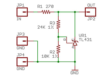
The circuit is as simple as it gets. It uses a TL431 programmable voltage reference configured for an 8.5V cutoff. If you're not comfortable having VPP so close to the specified maximum, you can adjust the voltage divider (R2 and R3) to reduce the cutoff. Keep in mind that the minimum VPP for the new PIC18 devices is VDD + 4.5V. This means that if you're powering your PIC from 3.3V (the maximum VDD), the minimum required VPP is 7.8V.
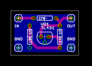
To build the circuit, you can use a small piece of prototyping board. I solder right-angle headers into the ground pads so that the limiter can be inserted vertically, saving precious breadboard space.
I recommend testing the circuit after assembly. You’ll need a bench power supply (or any known 9V+ voltage source) and a voltmeter. Follow this procedure with the bench power supply:
- Set your power supply to its minimum voltage and current.
- Set the voltmeter range to 20V DC.
- Connect the circuit's IN to the power supply, OUT to the voltmeter, and tie all three grounds (power supply, voltmeter, and circuit) together.
- Increase the power supply voltage gradually. If it shows an overcurrent condition, increase the current slightly (but only a little—30 mA is the threshold where you should start checking for shorts).
- The voltmeter should track the power supply voltage until it reaches 8.5V. At that point, the output should stabilize. Continue increasing the power supply voltage to around 12.5–13V. If the voltmeter still shows 8.5V, your circuit is functioning correctly.
Once you've confirmed the circuit works, it's time to use it. Connect IN to the MCLR/VPP signal from the programmer, OUT to the MCLR/VPP pin of your PIC, and GND to ground. This last connection is as essential as the other two—if ground is not connected, the circuit will pass the input voltage directly to the output.
Project files, including Eagle schematic and board layout, as well as Gerbers, are available in the Resources section.