Magnetic Probe Trigger Amplifier
When working with switching power supplies or high-frequency circuits, getting a clean, reliable oscilloscope trigger can be surprisingly tricky. Standard probes often struggle with noise and interference, especially when trying to capture small ripple or switching artifacts. Fortunately, there are clever solutions hidden in the deep archives of application notes. In this post, I’ll share a particularly elegant trigger probe circuit originally developed by Jim Williams, along with some practical tips for building and adapting it with modern, easily available components.
Recently, while researching low-noise DC-DC converters, I came across a clever and useful circuit in Linear Technology(now Analog Devices) Application Note 70 (local copy). The concept involves sensing current in the converter's power inductor using a second inductor placed in close proximity. This sensing inductor is connected to a circuit that amplifies and conditions the signal, producing clean square-wave pulses suitable for triggering an oscilloscope sweep. The probe is electrically isolated from the main circuit, preventing measurement interference. As a bonus, the analog output of the probe amplifier allows you to observe the current waveform through the power inductor.
To get detailed information about the circuit operation please read the application note. Circuit description starts at page 37.
Some of the parts used in the original circuit are difficult or nearly impossible to source. The sensing inductor specified in the application note is no longer available. I tried several different unshielded 1 mH inductors, and they all worked well. My favorite is the Xicon 434-1120-103K, available from Mouser. Its axial construction makes it easy to solder to a cable, and it can be conveniently placed inside a piece of copper pipe to make the probe more directional.
The CA3096 transistor array was discontinued a long time ago. I substituted it with the Fairchild FMB3904 and FMB3906. While they’re not matched pairs, they perform well. Philips makes a pin-compatible matched variant of these transistors, which I plan to try in the next board revision to see if it makes any difference.
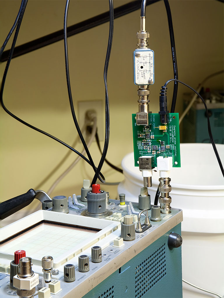
As is often the case with application notes, the circuit description and build details are somewhat brief. I'm sharing my notes in the hope that they’ll be helpful to other builders. I also made a few minor modifications to the schematic, primarily for clarity. Project files are available in the Resources section of this website. This is a preliminary version—I'm planning to re-route the board to make it easier to mount on the oscilloscope’s external trigger connector. As you can see in the title image, the analog output (the shiny BNC connector on the lower left) is unusable unless the external trigger input is located at the corner of the oscilloscope’s front panel, as it is on the Tektronix 475A.
Also visible in the title image is the probe compensation box. Fortunately, I had one from years ago—new ones, available from various parts distributors, are ridiculously expensive. Buying an old probe on eBay and cannibalizing it for its compensation box is a much more economical option. If you go this route, don’t plan on using the original cable attached to the box, as it’s not standard coax and won’t perform well. Another good source for small metal boxes with BNC connectors is the used RF measurement equipment section on eBay.
The last part of the setup—the power supply for the amplifier—can be handled in several ways. The simplest option is to use the 5V provided by the Tektronix oscilloscope's probe power connector. Wall warts also work well.
Using the probe is straightforward. First, connect the analog output to a 50-ohm oscilloscope input with the attenuator set to 0.5 V/div, and connect the digital output to the oscilloscope’s external trigger input. Place the probe inductor near the power inductor and observe the current waveform. Adjust the spacing to achieve a good peak-to-peak amplitude without clipping. Check the digital output—you should see a 5 V peak-to-peak square wave, in phase with the input signal crossing its midpoint. You can now use the digital output to trigger the scope while observing the converter’s output noise (which—if your PCB layout is good—is typically too weak and fuzzy to provide a reliable trigger on its own).
Of course, the probe amplifier can be used to condition not only inductor output but any other signal which won’t overload the input stage. Upper frequency limit is approximately 20MHz. I highly recommend building this circuit and playing with it – it is a useful aid to many common types of oscilloscope measurements.