Low cost step-up-down 120ma DC-DC converter
Today's electronic projects often require multiple supply voltages. For example, 5V is commonly used to power microcontrollers (MCUs), while sensors and peripheral interface controllers typically operate at 3.3V. If your circuit includes both types of components, both voltages must be provided. Usually, one voltage is derived directly from the main power source (such as a battery or wall adapter), and the second voltage is generated from the first—using either a linear LDO regulator if it is lower, or a boost converter if it is higher.
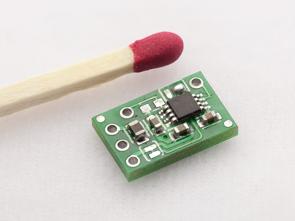
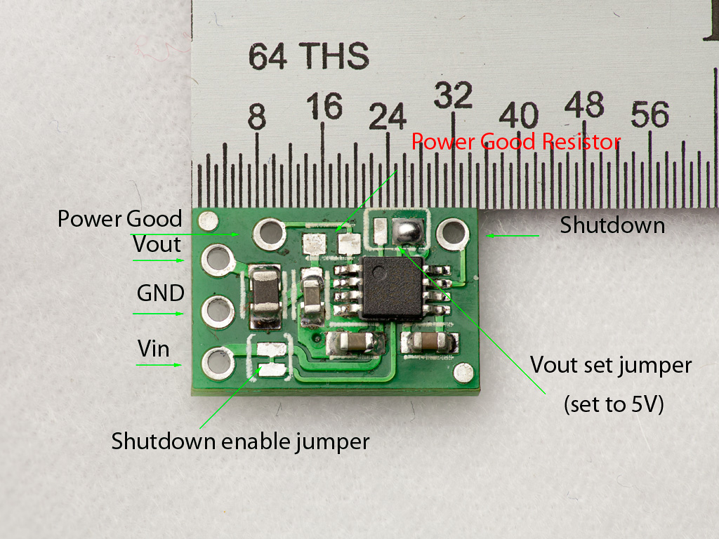 The boost converter I’ve designed uses the Microchip MCP1253 charge pump controller. It operates without an inductor and can provide a selectable output voltage of either 5V or 3.3V, with up to 120 mA of output current. The converter measures just half an inch in length and weighs only 0.5 g. All through-hole pads are arranged on a 0.1″ grid, making it breadboard-friendly. Thanks to its inductorless design, the converter is inexpensive, stable, and easy to use. It automatically switches between step-down and step-up modes and offers additional features such as external shutdown and supply voltage monitoring. The picture on the left shows the board connections.
- Vin, Vout, and GND are the only necessary connections out of the box (they are marked on the reverse side of the PCB). The input voltage can range from 2.0 V to 6.0 V, and the output voltage is set to 5 V by default. The converter automatically switches between buck and boost modes. This allows, for example, a regulated 5 V output across the entire discharge range of four alkaline cells (3.6–6 V), or 3.3 V from a single LiPo cell (if the output voltage is switched to 3.3 V—see below). The output current is 120 mA, maintained down to 2.8 V input at 5 V output.
- Vout Set Jumper: The 3-pad output voltage selection jumper is set to 5 V by default by shorting the middle pad to the right pad. To switch the output to 3.3 V, remove the existing solder bridge using solder wick and short the middle pad to the left one.
- Shutdown: The converter can be disabled by pulling the Shutdown signal low. By default, this pin is hardwired to Vin. To use it, cut the trace inside the Shutdown Enable jumper. You can later re-enable it by closing the jumper again, similarly to the output voltage selector.
- Power Good: This signal goes low when the output is out of regulation, indicating a low battery or excessive load. To enable this feature, solder a 100 kΩ 0603 resistor to the vacant pads marked by the arrow labeled Power Good Resistor.
Project files are available for download in the Resources section.