Interfacing a Character LCD via SPI
Introduction
Modern microcontrollers are packed with memory and processing power, but often don't have enough pins for everything we want to connect. A classic example is driving an HD44780-compatible LCD display — a great choice for simple user interfaces, but one that normally demands a lot of I/O lines. In this project, I'll show you how to control one of these displays over a simple SPI connection, using just a handful of wires and a cheap shift register. We'll build a tiny daughterboard to handle the conversion, set up a minimal breadboard circuit for testing, and walk through exactly how to send data to the LCD. Along the way, I'll also point you toward some tools that make experimenting even easier.
As time goes on, microcontrollers just keep getting more powerful, cheaper, and smaller. Not too long ago, a typical microcontroller might have had 40 pins and no internal memory at all. Fast forward to today, and modern J-series PICs pack 96K of program memory into a tidy 28-pin package. That's plenty of memory to drive all sorts of peripherals — but now we're running short on pins.
In this article, I’ll show you how to drive a parallel-interface peripheral using a serial connection. A perfect example? An HD44780-compatible LCD module. It's popular, inexpensive, and slow enough that you won't lose any speed converting parallel to serial. Plus, using fewer pins means you might even save a few bucks by being able to use a smaller microcontroller package.
SPI makes this super easy, especially now that newer PICs have built-in support for synchronous serial communication. On the LCD side, the only extra hardware you'll need is a 74HC595 double-buffered shift register. You can pick one up from online distributors like Mouser or Digi-Key for as little as 48 cents in an SMT package (a bit more for DIP). It’s a really simple device, not by itself capable of driving anything so most of the magic will happen in software.
An HD44780-compatible LCD (or just “LCD” for short) is a parallel device. It has 8 data lines and 3 control signals that tell the controller when the data is valid, what kind of data it is, and whether you're writing to or reading from the display (spoiler: we won’t bother with reading from an LCD in this setup). SPI, on the other hand, is serial — it sends one bit at a time, "marking" each bit with a clock pulse. The 74HC595 receives the SPI data and spits it out on its parallel outputs.
Take a look at the 74HC595’s schematic symbol. It actually has two buffers — one for serial input, and one for parallel output. Serial data goes into pin 14, and the serial clock comes in on pin 11. When pin 12 transitions from low to high, the data from the serial buffer is copied over to the parallel outputs. This animation shows two example bytes — 0x55 (0101 0101) and 0xAA (1010 1010) — moving from SPI to the parallel pins.
Before we dive deeper, let’s quickly talk about the LCD's native interface. The display has 8 data lines and 3 control lines. It can operate in either 8-bit or 4-bit mode. In 8-bit mode, all the data lines are active and control is a bit simpler — but we'd quickly run out of outputs on our shift register. In 4-bit mode, only the upper 4 data lines are used. Each data byte is split in half and sent in two pieces. That’s the mode we’ll be using.
The control signals are RS, RW, and E. RS tells the LCD whether you're sending a command or character data: if RS is 0, it’s a command; if RS is 1, it’s character data. A falling edge on E triggers the LCD to latch in the current data and RS state. The RW signal controls whether you're reading from or writing to the LCD — but since we're using a one-way shift register, we won't be able to read anything back. So we'll just tie RW to ground and wait long enough between writes to make sure the LCD keeps up.
Hardware
Building the SPI-to-LCD Daughterboard
The SPI-to-LCD circuit lives on a small daughterboard. The idea is simple: attach it directly to the LCD module and run just three signal wires and two power wires back to the main board with the microcontroller. The daughterboard is designed to plug into the standard LCD 2×7 header. Here’s the schematic.
Setting Up the Main Board
To keep the focus on LCD communication, the "main board" with the MCU is kept very simple. It’s just the ever-popular PIC18F4520 mounted on a breadboard — no crystal oscillator needed. Here’s the schematic for the breadboard setup.
Sending Data to the LCD
So what exactly do we need to do to send a byte to the LCD?
First, we set RS and the high nibble of the data byte. Then, we toggle E: set it high, then low. (The LCD latches the data bus on the falling edge of E.)
Next, we set the low nibble of the data and toggle E again. After that, we need to wait a short while before sending the next byte. The exact delay depends on the particular HD44780 clone you're using, but for most modules, about 1 millisecond is enough.
The animation above illustrates the sequence. Open the image to better see the animation.
Further Reading
There are already plenty of great resources online that dive into the low-level details of controlling HD44780-based LCDs, and I don't want to reinvent the wheel here. If you want to dig deeper, I highly recommend this LCD simulator — it lets you experiment with LCD signals and see the results in real time. Definitely give it (and the related pages) a try if you want to learn more about how the LCD control signals work under the hood.
Software: Definitions
Let's discuss the software that drives the circuit. I prefer to use C language, and the code examples here have been verified to compile and run with the Microchip C18 compiler.
The code is mostly standard C, with some custom typedefs — for instance:
BYTEstands forunsigned charWORDstands forunsigned int
The focus here is not on clever tricks or ultra-efficient programming, but on demonstrating basic principles. You can find the complete code, including MPLAB project files, in the Resources section.
The code will work on any PIC18 microcontroller that has a built-in MSSP (Master Synchronous Serial Port, which supports SPI and I2C). You can pick any PIC18F chip — but if your chip has two MSSP modules, and you want to use the second one, you’ll have to adapt some variable names. For demonstration, I’ll use the PIC18F4520, and the provided MPLAB project is set up accordingly.
Tip: Using an in-circuit debugger (like Microchip’s ICD-2) can be extremely helpful. It lets you step through code and watch variables and registers in real time. If you use a different debugger, remember to update the project's Debugger settings.
Software: Shift Register Control
From the shift register's point of view:
- Every time you want to change any pin on the shift register, you must send the entire byte, not just the bit you changed.
- Therefore, we must track the last output state in a variable called
BYTE LCDpins;
(Recall that BYTE is just unsigned char, an 8-bit unsigned number.)
Here’s how the bits of LCDpins are mapped:
- Bits 4–7 → LCD data lines
DB4–DB7 - Bit 3 → LCD
E(Enable) pin - Bit 2 → LCD
RS(Register Select) pin
We want to change individual pins without disturbing the others. We'll use bit operations for that. First, define some masks:
    #define RS  0x04    // RS pin mask (bit 2)
    #define E   0x08    // E pin mask (bit 3)
Then define some macros to set or clear these pins:
    #define SET_RS  LCDpins |= RS
    #define CLR_RS  LCDpins &= ~RS
    #define SET_E   LCDpins |= E
    #define CLR_E   LCDpins &= ~E
How it works:
OR (|=)sets a bit without affecting others.AND (&= ~)clears a bit without affecting others.
Now in the code, you can simply write SET_RS; or CLR_E; to toggle those pins.
Updating the 4 Data Lines
When sending 4-bit data:
- Clear the upper nibble first:
LCDpins &= 0x0f; // preserve only lower 4 bits
- Insert the upper nibble from your data byte:
LCDpins |= ( tosend & 0xf0 );
- Then send it over SPI.
For the lower nibble:
- First clear upper nibble again:
LCDpins &= 0x0f;
- Then shift the lower nibble into place:
LCDpins |= ( tosend << 4 ) & 0xf0;
Last note: We also define the RCK (latch) pin like this:
#define RCK PORTEbits.RE0
This lets you change the pin assignment easily later by editing just one #define.
Software: Low-Level Functions
SPI Initialization
The sequence to send a byte to the LCD is:
- Initialize SPI to work with 74HC595.
- Set RS low for command or high for data.
- Set E low, copy high nibble of a command or data byte to high nibble of LCD variable.
- Send LCD variable to SPI.
- Set E high.
- Send LCD variable to SPI.
- Set E low.
- Send LCD variable to SPI.
- Copy low nibble of a command or data byte to high nibble of LCD variable.
- Send LCD variable to SPI.
- Set E high.
- Send LCD variable to SPI.
- Set E low.
- Send LCD variable to SPI.
There is lot of repetitions here. Let’s make our life a little easier and write some functions. First of all we need to have something to talk to SPI hardware on a PIC. As I said before, SPI is easy. We will need two functions – one for initializing SPI and another to send a byte. The following SPI initialization function is part of the standard library included with Microchip C18 compiler.
Here’s the function to initialize SPI for the 74HC595 shift register:
/* SPI initialization */
/* Borrowed from Microchip library. I heard they are going to stop providing peripherals support code in future
    releases of C18 so I made a local copy just in  case */
/*  sync_mode:
              SPI_FOSC_4        SPI Master mode, clock = FOSC/4
              SPI_FOSC_16      SPI Master mode, clock = FOSC/16
              SPI_FOSC_64      SPI Master mode, clock = FOSC/64
              SPI_FOSC_TMR2  SPI Master mode, clock = TMR2 output/2
              SLV_SSON SPI    Slave mode, /SS pin control enabled
              SLV_SSOFF SPI   Slave mode, /SS pin control disabled
    bus_mode:
              MODE_00       SPI bus Mode 0,0
              MODE_01       SPI bus Mode 0,1
              MODE_10       SPI bus Mode 1,0
              MODE_11       SPI bus Mode 1,1
    smp_phase:
              SMPEND        Input data sample at end of data out
              SMPMID        Input data sample at middle of data out
*/
void init_SPI ( BYTE sync_mode, BYTE bus_mode, BYTE smp_phase )
{
  SSPSTAT &= 0x3f;
  SSPCON1 = 0x00;
  SSPCON1 |= sync_mode;
  SSPSTAT |= smp_phase;

  switch( bus_mode ) {
    case 0: SSPSTATbits.CKE = 1; break; // Mode 0,0
    case 2: SSPSTATbits.CKE = 1; SSPCON1bits.CKP = 1; break; // Mode 1,0
    case 3: SSPCON1bits.CKP = 1; break; // Mode 1,1
    default: break; // Mode 0,1 (default)
  }

  switch( sync_mode ) {
    case 4: TRISAbits.TRISA5 = 1;
    case 5: TRISCbits.TRISC3 = 1; SSPSTATbits.SMP = 0; break;
    default: TRISCbits.TRISC3 = 0; break;
  }

  TRISC &= 0xDF; // SDO output
  TRISC |= 0x10; // SDI input
  SSPCON1 |= SSPENB; // enable SSP
}
To initialize SPI for 74HC595, call:
init_SPI ( SPI_FOSC_4, MODE_00, SMPMID );
SPI Write
To send a byte via SPI:
BYTE wr_SPI ( BYTE data )
{
  SSPBUF = data;
  while( !SSPSTATbits.BF );  // Wait for transmission complete
  return ( SSPBUF );
}
(You must read SSPBUF to clear the SPI buffer flag.)
Sending Data to the Shift Register
To send current LCDpins state to the shift register:
void SPI_to_74HC595( void )
{
    wr_SPI ( LCDpins );
    RCK = 1;    // latch data
    RCK = 0;
}
Sending Data to the LCD
To send a full byte (in 4-bit mode) to the LCD:
void LCD_sendbyte( BYTE tosend )
{
    LCDpins &= 0x0f;
    LCDpins |= ( tosend & 0xf0 );
    SET_E;
    SPI_to_74HC595();
    CLR_E;
    SPI_to_74HC595();

    LCDpins &= 0x0f;
    LCDpins |= ( tosend << 4 ) & 0xf0;
    SET_E;
    SPI_to_74HC595();
    CLR_E;
    SPI_to_74HC595();
}
Macros for Commands and Characters
#define LCD_sendcmd(a)  { CLR_RS; LCD_sendbyte(a); }
#define LCD_sendchar(a) { SET_RS; LCD_sendbyte(a); }
Use LCD_sendcmd(x) to send a command, and LCD_sendchar(x) to send a character.
LCD Initialization Sequence
To properly initialize the HD44780 LCD in 4-bit mode:
void LCD_init ( void )
{
  CLR_RS;
  RCK = 0;
  Delay10KTCYx ( 20 ); // wait 100ms

  // send 0x3 three times
  for (int i = 0; i < 3; i++) {
    LCDpins = 0x30;
    SET_E; SPI_to_74HC595(); CLR_E; SPI_to_74HC595();
    Delay10KTCYx(2); // wait 10ms
  }

  // send 0x2 to switch to 4-bit mode
  LCDpins = 0x20;
  SET_E; SPI_to_74HC595(); CLR_E; SPI_to_74HC595();

  Delay1KTCYx(2);
  LCD_sendcmd(0x28); // 4-bit, 2-line, 5x7 font
  Delay10KTCYx(1);
  LCD_sendcmd(0x01); // clear display
  Delay10KTCYx(1);
  LCD_sendcmd(0x0c); // display ON, cursor OFF
  Delay10KTCYx(1);
  LCD_sendcmd(0x06); // entry mode set
}
Important:
- Initialization starts with the LCD still thinking it’s in 8-bit mode.
- Timing delays assume an 8MHz clock. Adjust delays if you use a different clock speed.
- Delays use standard Microchip delay functions (
Delay10KTCYx, etc.).
Software: High-Level Functions
Send a String
void LCD_send_string( const rom char *str_ptr )
{
    while (*str_ptr) {
        LCD_sendchar(*str_ptr++);
    }
}
Usage example:
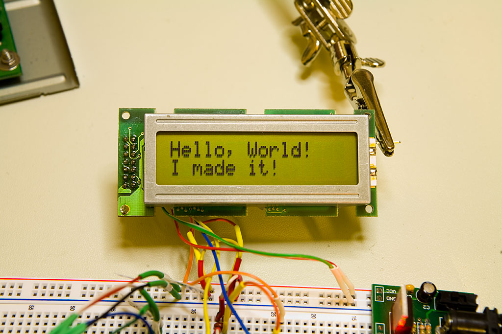
const rom char *const rom hello = "hello, world\n";
LCD_send_string( hello );
prints “hello, world” on the LCD.
Send a Byte as Two Hex Characters
To output a byte as two ASCII hex characters:
void LCD_send_hexbyte ( BYTE data )
{
    BYTE temp = data >> 4;
    if ( temp > 9 ) temp += 7;    // adjust for 'A'-'F'
    LCD_sendchar ( temp + 0x30 );

    temp = data & 0x0f;
    if ( temp > 9 ) temp += 7;
    LCD_sendchar ( temp + 0x30 );
}
The last function demonstrates usage of LCD commands. It clears the screen and returns the cursor to the home position.
void LCD_Home( void )
{
    LCD_sendcmd( LCD_CLRSCR );
    Delay10KTCYx(1);
    LCD_sendcmd( LCD_HOME );
}
As you can see, there is a delay inserted after the “Clear screen” command. This delay is essential; we need to wait that long before sending other data to the display to satisfy timing requirements.
Many commands can be used as-is without writing additional functions. For example, very often we need to print at the second line of 2-line display by moving the cursor to position 0x40. This can simply be done by calling:
LCD_sendcmd( 0xc0 );
The “set cursor” command code is 0x80 + address. 0x80 + 0x40 is 0xc0. Alternatively, since “set sursor” command is defined in the header as SET_CURSOR, we can write the previous call as:
LCD_sendcmd( SET_CURSOR + 0x40 );
Now it’s time to run our code.
Wrapping up
Driving an HD44780-compatible LCD over SPI is a simple, elegant solution to the problem of limited microcontroller I/O. With just a shift register and a little bit of careful timing, you can free up valuable pins for other uses without sacrificing functionality. I hope this guide gives you a solid foundation to start experimenting with your own SPI-to-LCD setups — whether you're building a quick prototype or a polished final project. As always, feel free to tweak, adapt, and expand on these ideas to fit your own designs. Happy hacking!