Hantek DSO5000 series oscilloscope modification – doubling the bandwidth of DSO5102B.
Some time ago, I realized that I needed to add a digital oscilloscope to my set of instruments. A DSO is handy for making measurements and capturing screenshots—something I've been doing a lot lately. After comparing the specifications of current models from several manufacturers, I chose the Hantek DSO5102B. The main reasons for selecting this model were its cost, screen size, and strong potential for hacking—though not necessarily in that order.
Hantek DSO5000-series scopes come in three bandwidth variants: the DSO5062B (60 MHz), DSO5102B (100 MHz), and DSO5202B (200 MHz). These models are identical—or nearly identical. Early production units with different bandwidths had different resistor values soldered into the analog front end, but that’s the only hardware difference. Converting one model to another is simply a matter of editing certain configuration files inside the scope.
In addition, many other modifications are possible, including adjusting fan speed, upgrading to a low-jitter ADC clock, improving power supply noise performance, and more (see the EEVblog thread for details). Newer benchtop DSO/MSO oscilloscopes from Hantek are based on the same hardware, and there have been successful attempts to convert this scope into an MSO by adding a logic analyzer PCB. Das Oszi project is also a good source of information on this subject.
As is often the case with Chinese-made products, this oscilloscope is also sold under other brand names, including Tekway, Voltcraft, and several others, with model numbers that differ from Hantek’s. The firmware was originally developed by Tekway and uses Tekway model numbers: DST1062B (60 MHz), DST1102B (100 MHz), and DST1202B (200 MHz). Among the various brands, Hantek tends to be the cheapest. Additionally, in the U.S. (where I live), Hantek units are available from local sellers. Interestingly, when I was shopping around, the 60 MHz models were more expensive than the 100 MHz versions, so I ended up purchasing a DSO5102B from Hong Kong for $388.88, shipped via UPS Global Express.
After receiving the instrument, I verified its functionality. The scope worked well, the screen was large, and the bugs were tolerable. I then proceeded to "upgrade" the device to the 200 MHz model. What follows is a detailed description of the steps I took to implement the modification outlined in the EEVblog thread (Tinhead, you're the man!)—proceed at your own risk!
The instrument has no "warranty void" stickers, and I'm assuming that opening the case is acceptable from a warranty standpoint, although I never actually verified this. In the worst-case scenario, the device would need to be shipped to the seller or manufacturer for repair or replacement. Also, note that this procedure involves operating the device with the power supply exposed—please exercise caution!
Step 1: Backup
 The first step before making any firmware modifications is to establish a known good state in case the modification fails and a rollback is necessary. The backup is saved to a USB flash drive.
Start by downloading the Tools_B_models.zip archive, extracting it, and reading the how_to_backup.txt file located in the Backup_B_models subdirectory. Then, copy the dst1kb_b_backup_tool.up file to an empty USB flash drive (128 MB or larger), and insert the drive into the USB port on the front of the oscilloscope.
Wait for the floppy disk icon at the top of the screen to turn blue, then press the “UTILITY” button, followed by “F2.” Although the function is labeled “Firmware Update,” the file on the USB drive does not perform an update—we are only making a backup. Follow the on-screen instructions and wait for the backup to complete (it may take a while—don’t panic). Once it's finished, copy the contents of the flash drive to a safe location.
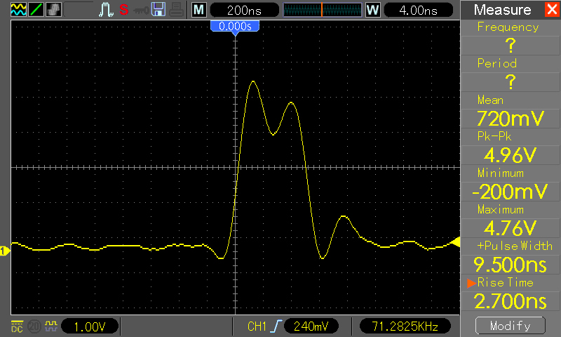
It’s also a good idea to test the instrument’s capabilities before performing the modification. To do this, I connected a very fast pulse generator (with a rise time of less than 100 ps) to Channel 1 of the scope and captured the measurement shown in the screenshot on the left. Note the timebase setting (displayed in the top row, to the right of the letter "W")—4 ns, which is the fastest setting available on the 100 MHz model.
Step 2. The Mod
As I mentioned earlier, the 60, 100, and 200 MHz scopes are essentially identical; changing the bandwidth involves modifying a few files. The scope runs Linux internally, and a serial console connection is available on the main PCB.
To access it, I needed to:
- a) remove the case, and
- b) remove the EM shield from the main PCB.
The case is easy to remove—just unscrew four screws: two located next to the retractable front legs, and two more under the carrying handle.
The shield is secured by five screws—two at the top and three at the bottom. Once the screws are removed, the shield can be pulled off without much difficulty. With the screen facing away from you, the input stages are located on the left, beneath another shield, and the console connector is to the right of the input stages.
 Since I was curious about the input stages, I removed their shield as well and took a picture. What I needed to determine were the values of certain resistors around the variable gain amplifier—see the EEVblog thread linked above for a detailed discussion.
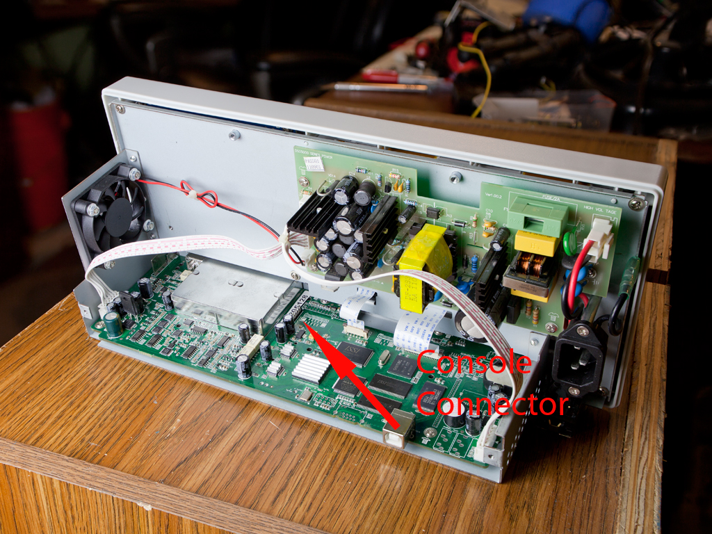
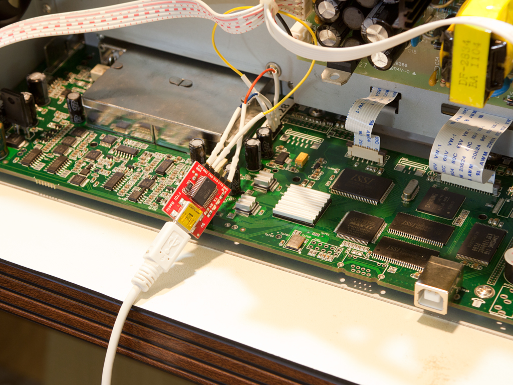
The picture on the right shows the oscilloscope with the case and shield removed. An arrow points to the location of the console connector.
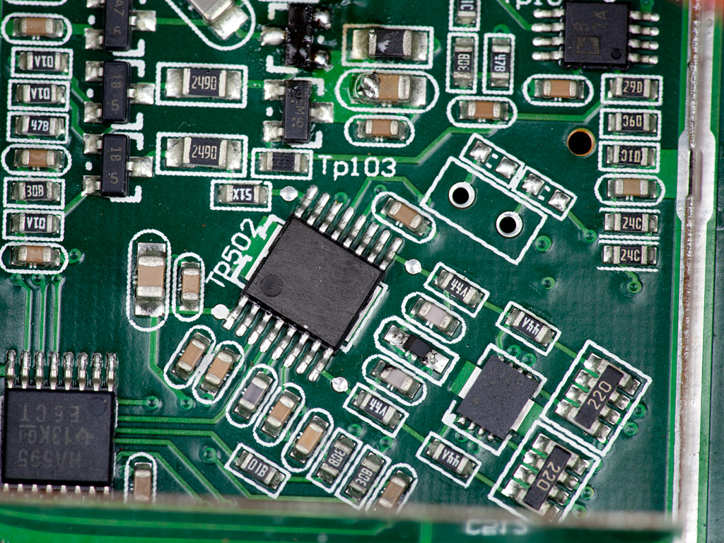
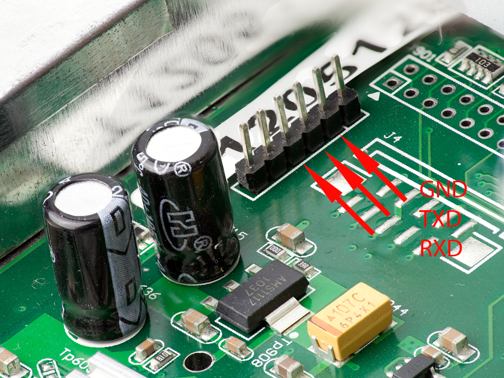 The next picture is a close-up of the connector. In my unit, this spot is populated with a pin header, making the connection very straightforward. The positions of the relevant signals are labeled—they need to be connected to a 3.3 V USB-to-serial TTL converter. Note that the Tx pin on the oscilloscope must connect to the Rx pin of the converter, and the Rx pin on the oscilloscope must connect to the Tx pin of the converter. This photo shows the converter connected to the board.
Now it's time to start hacking. Open a terminal session connected to the USB-to-serial converter’s COM port using the following serial settings: 115200 baud, 8 data bits, no parity, 1 stop bit (8N1). Then, apply power to the oscilloscope. Be very careful—parts of the power supply will be exposed!
A key rule when working around exposed mains voltage is to always work with one hand to reduce the risk of electric shock. However, because the instrument is lightweight, it's difficult to press buttons or plug anything in using only one hand. Here’s how I handled it: First, I made sure the power cord was unplugged at both ends. Then, I pressed the power button in. Finally, I connected the instrument end of the power cord, and then plugged in the other end. This way, I never touched the powered device directly.
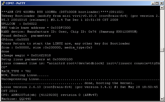
At this point, the oscilloscope will begin booting the Linux OS. After a short while, the output will stop. Pressing Ctrl-C produced the following message:
Please press Enter to activate this console
I pressed Enter, and a console prompt appeared on the screen:
[root@Tekway-dso /]#
We are now in the root directory. Enter ls command. My (already hacked) root directory looks like this:
[root@Tekway-dso /]# ls
OurLanguages      fpgabank.conf     lost+found        tdc_edge125M
bin               help.db           mnt               tdc_overtime125M
chk_base_volt     home              msg               tdc_pulse125M
cur_acq.type      i2c.log           mult_adc.log      test
dev               icon              nfs               tmp
disk_sta.info     keyprotocol.inf   opt               tmpdst
dn.rbf            language.img      param             ubdb.swi
dso               lib               proc              usbsavefile.tmp
dso.exe           linuxrc           protocol.inf      usr
dst1202b          logo              sbin              var
etc               logotype          sys.inf
fpga.exe          logotype.dis      tdc.log
[root@Tekway-dso /]#
As can be seen, the directory contains a file named dst1202b—this file tells the firmware to treat the hardware as a 200 MHz instrument. Lower-bandwidth models will instead have a file named dst1102b or dst1062b. The file itself is empty; only the filename matters. The first step of the modification is to rename this file. For a 100 MHz scope, the Linux command to do this is:
# mv dst1102b dst1202b
The next step is to modify four files to reflect the new model name. These files are: sys.inf, tmpdst, logotype, and logotype.dis. In the first three files, the string dst1102b must be changed to dst1202b. The fourth file depends on the vendor; in my case, it contained hantek_DSO5102B, which needed to be changed to hantek_DSO5202B.
The vi editor is available on the system, but it’s not very user-friendly. If you're unfamiliar with it, I recommend reading the manual and practicing on another Linux system first.
In each file, only a single character needs to be changed. The general keystroke sequence after opening the file is as follows:
- Use the arrow keys to position the cursor under the character
1that needs to be changed to2 - Press
r, then2 - Press
Esc, then type:wqand hitEnterto save and exit
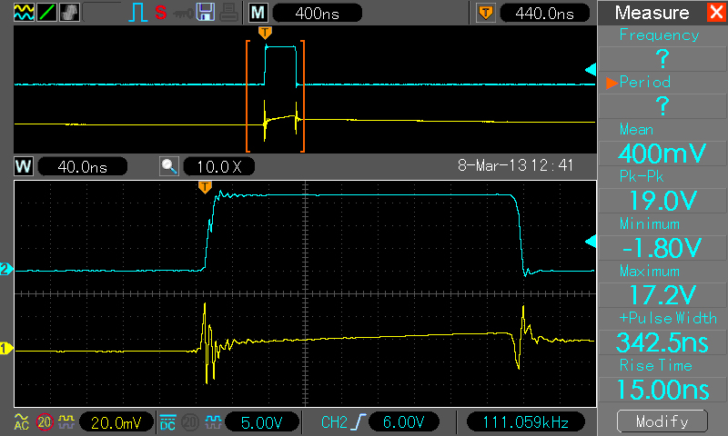
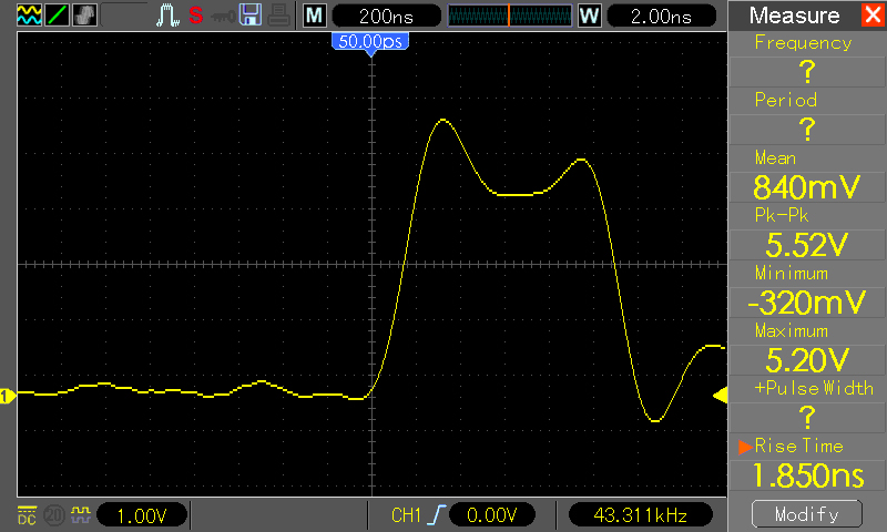 After all the files were modified, I simply rebooted the scope and enjoyed the increased bandwidth. The following screenshot shows the same fast pulse used in the baseline measurement. I now have access to the 2 ns timebase setting, and the measured rise time is approximately 1.8 ns—consistent with a 200 MHz bandwidth.