Cleaning of Tektronix AM503 Current Probe Amplifier
One of the most valuable instruments in my collection is the Tektronix current measurement system, which consists of an AM503 probe amplifier and the accompanying A6302 AC/DC probe. While the probe itself doesn’t need much attention beyond the occasional wipe to remove dirt from the jaws, the amplifier recently became quite noisy in several attenuator positions. So, I decided it was time for a thorough spring cleaning.
I followed a procedure I once found on a website dedicated to restoring Tektronix oscilloscopes. The author discussed fixing a fuzzy trace by cleaning the input attenuator contacts on a Tek 475. Unfortunately, I haven’t been able to locate the site again—if anyone has the link, please let me know so I can give proper credit.
The main areas that needed cleaning were the attenuator contacts and several range resistors: R206, R208, R212, R214, along with terminating resistors R204 and R216. For the cleaning, I used DeOxit D100L from Caig Laboratories and a piece of clean printer paper. A matchstick or toothpick can be helpful in tight spots—just don’t use anything metal; you don’t want to scratch that old Tektronix gold.
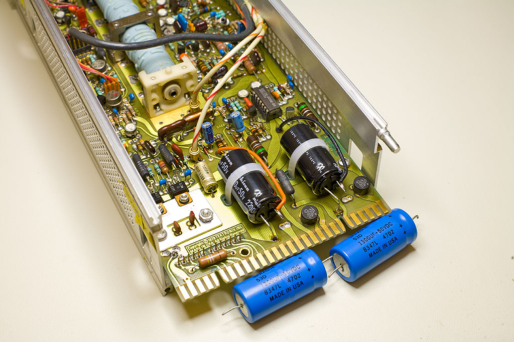
Since the power supply filter capacitors had dried out, I replaced them with a pair of fresh ones. I couldn’t find axial capacitors of the required capacitance, but fitting radial ones wasn’t too difficult. The result is shown in the title image. With that done, I unscrewed both attenuator covers and began the cleaning process.
Attenuator contacts are tiny, delicate, and difficult to replace. If you decide to follow this guide, be extremely careful around the contacts, especially when disassembling the range resistors.
Here’s the procedure for cleaning the attenuator contacts:
- Rotate the CURRENT/DIV switch or the AC-CAL-DC switch, depending on the contact you’re cleaning (the two contacts closest to the faceplate are operated by the AC-CAL-DC switch).
- Find a pair of adjacent switch positions—one that lifts the contact and one that lowers it.
- Tear a narrow strip of clean white printer paper.
- Place a drop of DeoxIT on the strip and let it soak in.
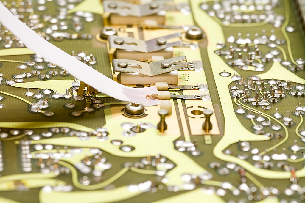
- Carefully place the dampened edge under the lifted contact, then lower the contact using the switch.
- Gently pull the strip horizontally from underneath the contact.
- Repeat this 3–4 times, then tear off the used edge, re-wet the strip, and move on to the next contact.
A picture above shows the correct paper placement.
When finished with one side of the board, flip the amplifier and continue on the other. These contacts are harder to access, as they’re located under the shaft—this is where the matchstick or toothpick comes in handy. You may also need to cut narrower strips of paper. Don’t forget the contacts near the faceplate, which are operated by the AC-GND-DC lever.
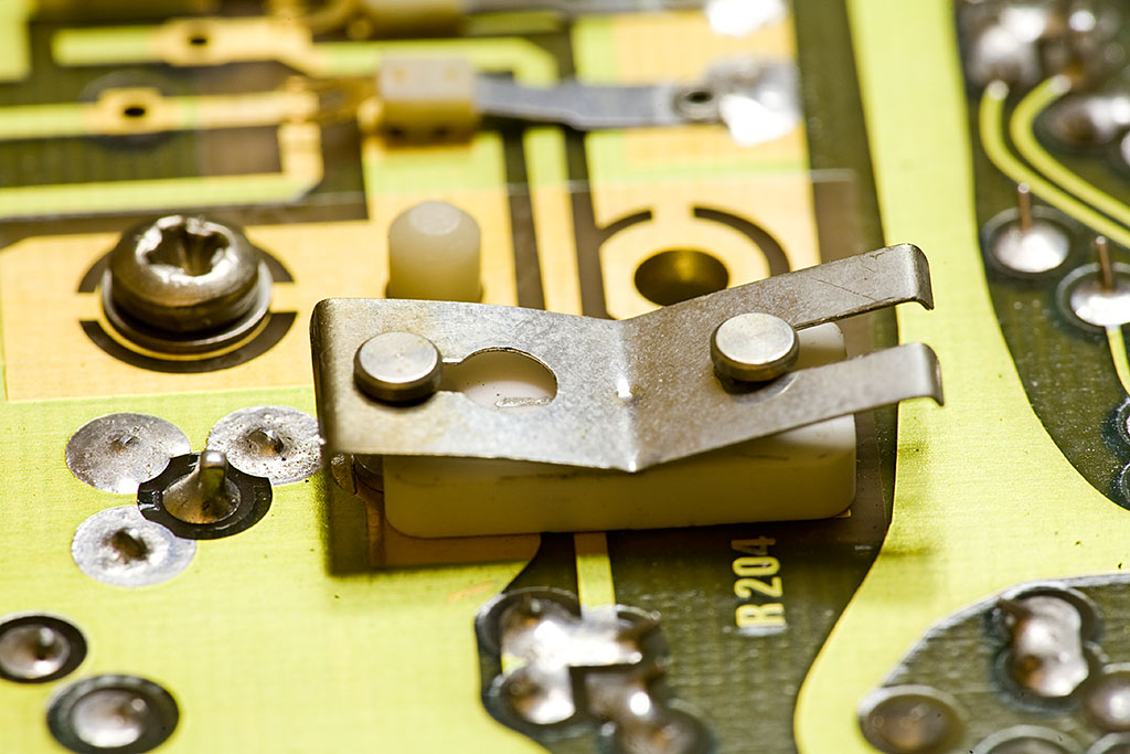
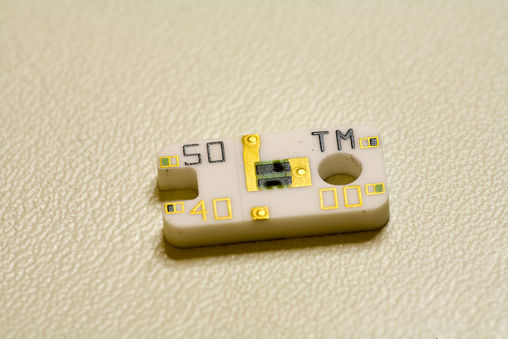
Once the contacts are clean, it’s time to clean the resistors. Since they have different values, it’s best to clean them one at a time. I’ll stress this again: be very careful when removing the springs—it’s easy to bend or break a nearby contact. If you're unsure of your dexterity, start with R204 (as shown in this image), since it's located farther from any contacts. Lower the retaining spring on both ends and gently pull it out, then remove the resistor from the PCB.
You can clean the PCB using a small piece of paper with DeoxIT. To clean the resistor itself:
- Place a clean sheet of paper on your work surface.
- Create a wet spot with DeoxIT.
- Lightly rub the resistor pads first on the wet spot, then on a dry section of the paper.
Reinstall the resistor and move on to the next one.
That’s it! If you like, you can apply DeoxIT Gold afterward — audio folks swear by its benefits for long-term signal quality. I tried it once a couple of years ago, and the oscilloscope I treated with it is still working great.
After the cleaning, my 25-year-old AM503 works like new.