Adjusting Inverter Control in Tektronix 7104 Oscilloscope Power Supply
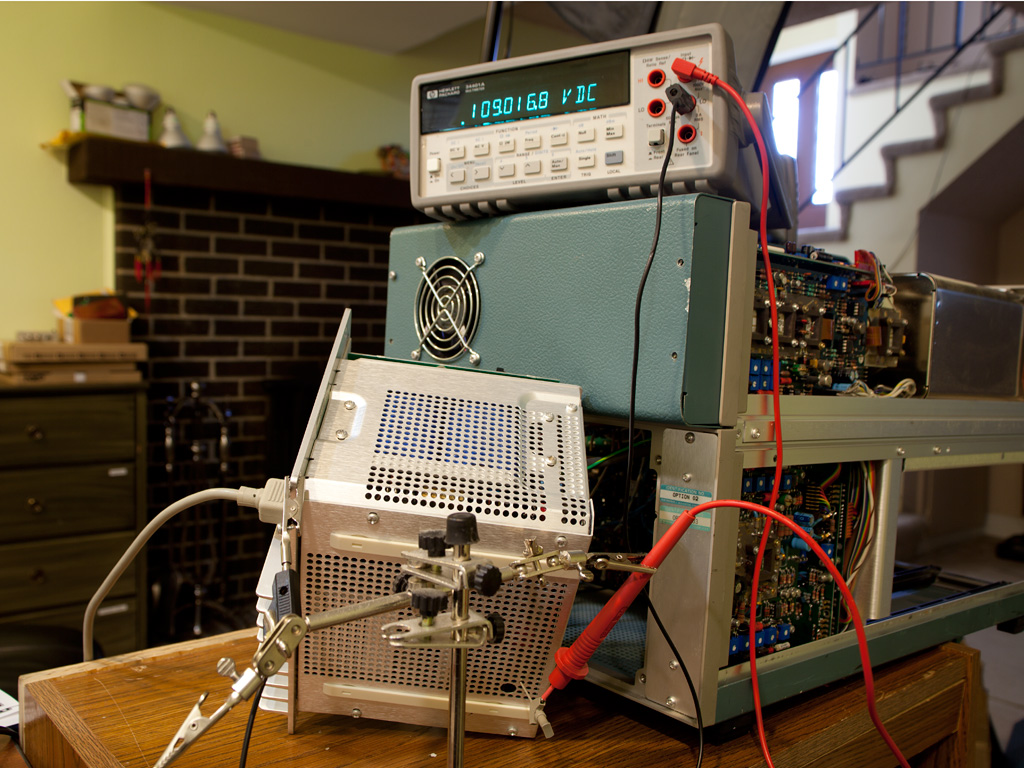
In this short article, I’d like to share a trick I learned today while checking the power supply of my trusty Tektronix 7104 oscilloscope. Step A2 of the calibration section in the manual calls for measuring and adjusting the pre-regulated 109V voltage at test point TP1326. Normally, accessing this test point requires removing the power supply cover, which takes time and exposes high voltages. The test setup shown in the title picture demonstrates how to access this test point while keeping the power supply cover in place.
The power supply cover is at ground potential, so do not attempt to reach the test point with a non-insulated probe. I used a Tektronix Klip Chip IC probe, threaded through a nearby ventilation hole, to grab the test point post. The post is clearly visible through a larger hole—typically used for adjusting potentiometer R1293. A flashlight comes in handy here.
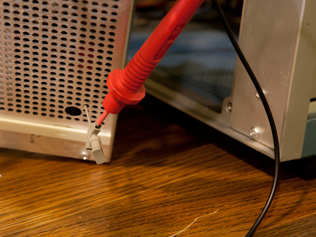
The next picture shows a close-up of the test connection. The probe is supported by a “third hand” tool—I wanted to monitor voltage fluctuations over the course of two hours to ensure it stayed within limits.
I hope this trick will be useful to anyone working on a similar power supply.